
| SinusLeistungsSteller - SLS Development/2006 |
|
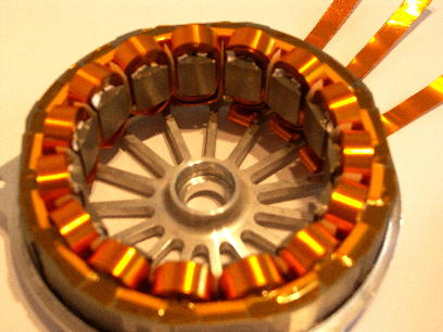
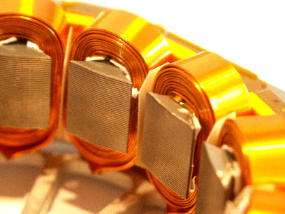
... subsequently the summary of 2006: 14.12.2006: Our motor has become improvements. We replaced the windings used in the 7kW run (2 parallel 1,5mm round-windings = 3,5mm²) by a copper band winding (2 times parallel 0,4*10mm = 8.0mm²!!). The copper winding alone weigh about 500g ... now we leave the model building scene ;-) 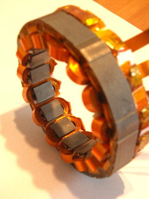
05.12.2006: The predator was equipped with a additional fan on its nose, to produce more airflow for its cooling. Now we can achieve powers more than 6kW for more than a minute (test was stopped when the motor reaches 100°C). A smaller propeller with 28" was used. This results in higher speed, 6.000rpm at a battery voltage of 49V. The test was performed with a SLS-60-200 without housing! The airflow produced from this fast rotating setup, is enough to cool the controller - without heatsink! The controller remained under 70°C. But the SLS had to be fixed properly in this airstream. 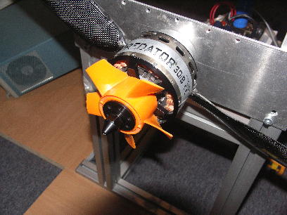
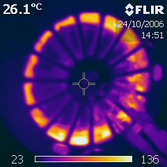
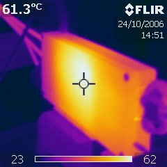
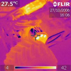
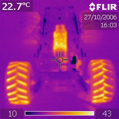
06.11.2006: ... Some nice pictures: During our tests we monitor the test-setup with our thermal camera. From that, a selection of the "most beautiful pictures" ... above on the left: our motor measured from the propeller side shortly after stopping from full load operation ... then: two images during our 7.000W-run (clearly visible, the small potting side in front is hotter than the bigger side of the alumininum housing ...) ... below we can prove, that Markus drives a "hot wheel" ;-) ... but this was already known! In the monstertruck we used a SLS-60-100 without alu-case. Only a shrinking tube protected the electronic against dirt. Meanwhile we achieve very high efficiency, so we can think about a "light-version". 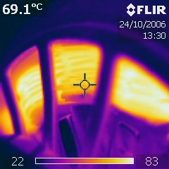
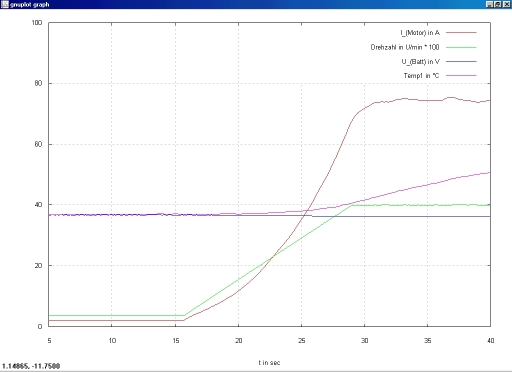
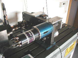
30.10.2006: The better thermal interface of the power modules exceeds our expectations. We broke the 7.000W-limit with a SLS-60-200! At a input voltage 53V the controller consumed about 132A and converted this power into 3.600rpm on a 40"-propeller. During this process the controller worked with a PWM-frequency of 20kHz in a operation point of about 80% partial load. As it can be seen in the picture, the motor current increased to about 103A(eff). We increased in steps of 60rpm up to 3.600rpm: ..3.420..3.480..3.540..3.600rpm. We were able to operate our motor only for 30 seconds under full load because it reached winding temperature over 150°C. The breaks inbetween were necessary, to cool down the motor to 50°C. We know that, this motor will be the weakest part in the chain of our future tests. Where can we get a motor with more torque/power??? The SLS (operating without additional heatsink!) run up to 75°C. This temperature was measured on the small side of the case (poor cooling). The bigger side of the case had only temperatures about 60°C. We will improve our next case by avoiding such asymetry. With additional heatsinks, we can imagine this power niveau also as continous power - since we prepare a additional improvement of the power modules interface. 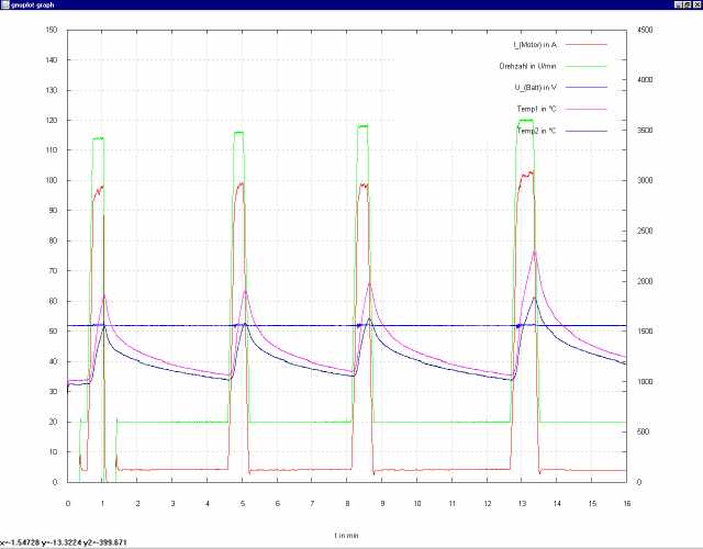
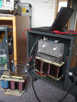
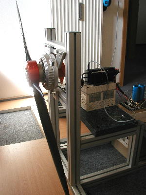
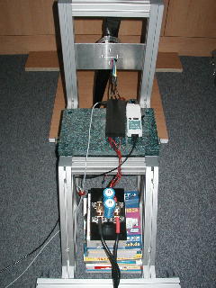
23.10.2006: Right below: our new DC-source - with a new (bigger!) trafo and rectifier. The old trafo can be seen on the floor. On the left: our second DC-source shown from the electronic side. We operate the DC-source from a (old - eBay!) notebook, via serial interface. We can preset the voltage from 0..65V, and the current limit from 0..200A. It is also possible to compensate the voltage drop on the supply lines, by increasing the output voltage depending on current flowing. All settings and actual values are shown on the notebooks display. If we have some more time in the future, we will build a battery simulator with settable cell characteristics (LIPO, NiMH, etc.) and presettable capacity (Ah). Of course, this only makes sense for stationary operation on test-benches - this DC-source can't fly ;-) ... please tell us if you have demand! 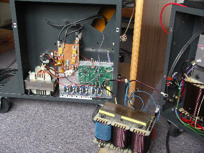
20.10.2006: We carried out some points in our "to-do-list" this week: the new DC-source is finished (projected are about 180A at 60V - lets see what is really possible ...) Then we got our first sample of the new SLS case. This will allow higher power in combination with a better power module (keyword: cooling), as first experiments (at lower power) already confirmed. In the next days/weeks we will build a few SLS-60-100 (-200) samples and measure them on our test-bench. Hopefully we will see that the motor is now the limiter for more power - the DC-source was it till now! 04.10.2006: Of course, the derating also works with LIPO-cells! Below a trace from a test with the 10S4P-block (about 8Ah) from Thomas Kalle´s helicopter, run on our propeller test-bench with a derating threshold of 31.6V and a shutdown threshold of 30.0V. It is nice to see, how the LIPO-cells stabilize the discharge time and drop very late. After reaching the derating threshold the propeller stopps relatively quickly, because only a small rest-charge is remaining in the batteries. Especially by the expensive LIPOs it is important, not to discharge too low in order to prevent damage of the cells or early degrade (reduction of charge cycles). Each LIPO-cells manufacturer has its own specification values for discharge level. With the SLS it is possible to set this threshold very precisely. 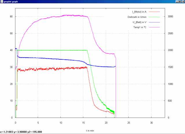
29.09.2006: The derating at empty battery was further improved. In the test shown below a NiMh-battery (30 cells, 3,2Ah) was discharged till the motor stopped with a derating threshold of 28,7V and a shutdown threshold of 25.5V on the propeller test-bench (40"-propeller at 1400 rotations/min). Till the derating threshold (28,7V) First the battery voltage follows the well-known discharge curve for constant power consumption. Then the consumed power from the battery is derated to prevent a low discharge of the battery. Finally the SLS shuts down the motor completely when the battery volatge drops below 25.5V - after that, the battery voltage recovers up to higher voltage (no load). The user has full control over this process - only the max. power is not available. The thresholds (derating and shutdown) can be set in steps of 0,1V. For nearly all (numbers and types) cells, a secure derating behaviour at almost complete usage of the available energy can be assured. 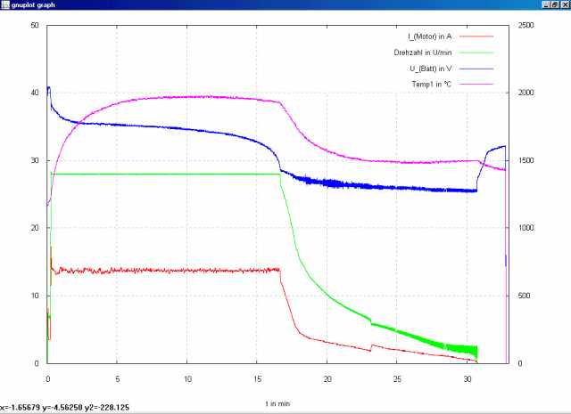
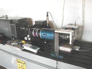
26.09.2006: Our first SLS-60 with new hardware was tested today. With the high-current-version (SLS-60-200) we achieved a power of 5.500W at (Uin=50V) at first attempt - but with additional heatsinks, which are glued from both sides on the SLS case and placed within the airflow. During the test, the SLS reached 80°C (measured next to a MOSFET); our motor run up to 110°C (measured in the winding). Conclusion: For more power, we need to improve the SLS-housing and the thermal interface of the power module and finally we need to mount the bigger three-phase current trafo into our DC-source. A bigger motor for load would be also welcome. Nevertheless, our selfmade motor suprised: it produced almost 14Nm at 3.300rpm! In our a opinion not a bad value for a inrunner with only 2kg and without gear (direct drive!). 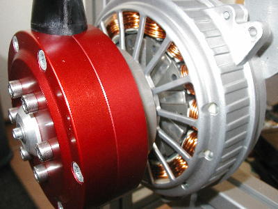
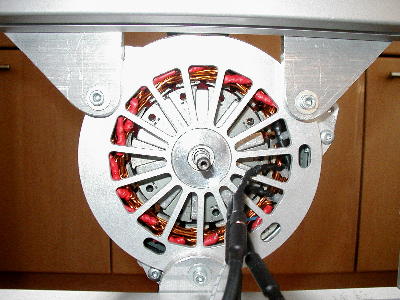
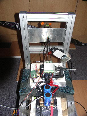
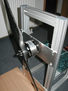
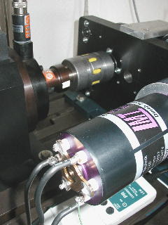
11.09.2006: We still don't have new SLS-60 hardware for our tests pending, but want to use the time to tune our own motor. For that, we mounted the propeller 40" in diameter with settable pitch to optimize the SLS parameter set for this configuration. On this setup the new 60V-hardware will be tested to the limits! The propeller actually belongs to a (man-carrying) ultralight airplain, but with suitable pitch we can test the SLS+motor up to maximum power. The used motor in origin is a industry motor, which we optimized/improved for usage with SLS. For this, we enlarged air in- and out-lets in order to enhance cooling and assure high permanent power. For the expecting high power throughput the SLS case (=heatsink) needs to be improved in the next weeks. Of course the power test will be performed outside! At this moment we are focused on startup behaviour and power levels up to 3kW. Next week, the new SLS hardware will be assembled. End of September (maybe begin of October) the hardware will be available. 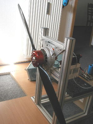
09.08.2006: Next week we can hopefully give the reworked SLS-60 PCB layout to the circuit board manufacturer. We expect the improved 60V-version mid of September. Further we hope to get the new (once more empowered) DC-source into work, because we run into limits again: the output voltage droped at the requested current! A bigger three phase trafo will be used - this should help a lot! :-) ... 04.08.2006: We reached the 5KW-limit with the 42V-controller (SLS-42-220). With a 28x12 propeller on the Predator we achieved 5.400rpm at constant voltage of 41v. After 3 minutes full load the SLS only got up to 75°C. The motor however, reached at the same time 100°C (on the winding), this forced us to stop the test. We assume, that we did still not reach the maximum power of the SLS! The 41V input voltage is not accessible when operated with 10S-LIPOs under load, but there is some more space left regarding controller temperature (the test was performed without additional heatsinks on the SLS!) and battery current. With the right motor and propeller combination, it should be possible to overcome 5kW. 12.07.2006: The availability of the 60V-version delays, because we have to make some changes on the PCB-layout. As a side effect, the trace memory is doubled to 512kByte. This means, nearly all data can be monitored (during flight) for one hour, in a resolution of 1/10 second! 11.07.2006: Because the SLS has no internal "spark protection" when plugged to the battery, we developed a small (23x15mm), external circuit which precharges the internal capacitors, before plugged in. This circuit is bridged after precharge by the main connector and produces no additional losses during flight. The precharge status (preload circuit) is indicated by a LED. Polarization of the supply lines is displayed by a second LED. Of course, we provide the aktive Vorladeschaltung (AVS) for free in combination with the SLS. The AVS also works with controllers from other manufacturers and can be obtained as a add-on for them. The AVS will be available in August. 20.06.2006: More information about the SLS can be found under "Highlights" (see top/left). Each highlight is clickable and opens a new window with additional information about the selected topic. 12.06.2006: We developed our software further in the last weeks and implemented the trace function. The uploaded values can be seen in the image below. We recorded the operation of the small SLS-42-110 with Predator on the propeller test-bench, over 10 min at 3,2KW. Indicated are the measured values for RPM, motor current (effective), MOSFET-temperature and DC voltage (we supplied with the DC-source, not with batteries). It can be seen how precise the RPM is controlled to 4.000rpm. The second picture shows the RPM-ramp transition from small speed up to 4.000rpm as a detailed view from the picture above. As theoretically expected, the motor current increases square with the rotation speed. The input voltage was 37V; the start temperature was 37°C. All measured values were monitored with a 100ms resolution - that means 10 values per second. The current oscillations in the controlled state are a result of different propeller air-inflow. The good control behaviour can be seen by that: the RPM remains constant! 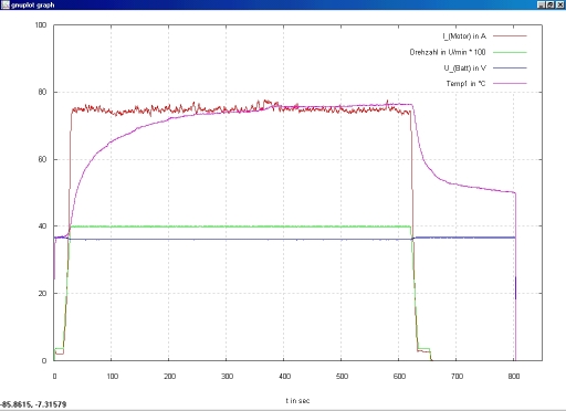
22.05.2006: The SLS-42-110 and SLS-42-22 is available from today on! Already ordered devices will be delivered immediately. 19.05.2006: A first prototype of the SLS-60-100 is finished and already in operation! The same applies for the new 60V-DC-source. Within the next days, we will start first tests the SLS-60-200! A 24h-continous power of 6KW as well as 10KW(+) peak-power should be possible with it ... 29.04.2006: Yesterday the PREDATOR and a carbon fiber propeller (30"x12") arrived! First measured values: with SLS-42-220: 4.400rpm at 35V with about 100A battery current. That means: 3.5KW power consumed! We were able to operate this configuration for a few minutes, without the SLS-42-220 (power module measured inside the case: max. 55°C) or the PREDATOR overheating! OK, the SLS was placed fully in the propeller airflow - nevertheless surprising! In "slow-mode" it rotates still at 50rpm, absolutely smooth - countable RPM! Startup behaviour was reliable and smooth even at low RPM! The PREDATOR has more power, because he cools itself very effectively - we could not measure more than 65°C. Only one deficit regarding the PREDATOR, the motor noise: At certain speeds at partial load the motor starts to scream, but at slightly higher or lower RPM runs more quietly. Probably some poorly damped mechanical resonances in the motor construction, which can be (hopefully) solved by Plettenberg. These resonances also occured during measurements on the generator test-bench ... We tested all on our propeller test-bench - THANK YOU ANDREAS! Because again the weather did not allow us to go outside, the test took place indoors(!). Conclusion: a very stormy and especially noisy story! We hope the weather will get better soon ... 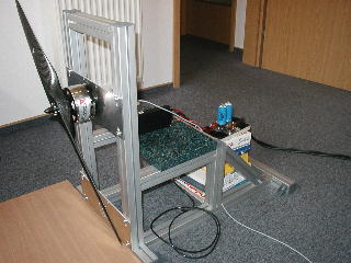
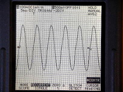
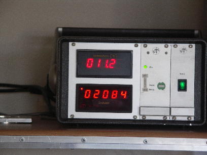
27.04.2006: The MOSFETs finally arrived! We will now produce the first devices of the SLS-42-xxx series and deliver the ordered devices. Beginning of May we will also test the first SLS-60-xxx prototype! 23.03.2006: The PCB layout of the 60V-version is finished and can be sent to the PCB manufacturer. We expect the first assembled circuit boards to arrive the week after eastern - first tests as planned in April! A trace buffer (256kByte) was added to the layout. With this we can record system values like motor current, temperature of power module, motor RPM and battery volatge during operation (flight) and display them graphically after readout. 13.03.2006: In the last weeks we focused on high RPM operation. Today we tested towards higher currents step by step. At a partial load of 7.500rpm, we pushed a LMT3060-8-14 to its current limit. The pictures document the test and the measurement results. The motor current was measured with a 100:1 current reduction. The torque-/RPM display shows the values of the slowly turning shaft - so after the reducing gear with 3,6:1 (11,2Nm at 2.084rpm resulting in about 2.450W). With a effective motor current of 175A we were able to produce over 300Ncm in partial load. without considering the gear losses! Of course we used a SLS-42-220 for this test, which we operated at only 80% of its theoretical current limit. The PWM-frequency remained constant at 25kHz. 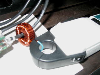
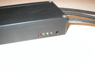
09.03.2006: The first design of the black anodized aluminum case for the series arrived today. The additional fans allows much higher permanent loads for the SLS! Besides a detail of the status-LEDs and the connector for the serial interface. 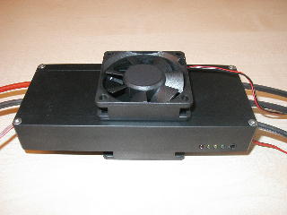
24.02.2006: Because of repeated requests: We will not be present at Sinsheim! But on saturday/3.11. or sunday/3.12. (maybe on both days) we will be part of the visitors. Of course we will bring along a SLS ;-) If someone is interested for a short meeting please contact us (info@SinusLeistungsSteller.de) to determine place and time. Because of unexpected long wait times of different components, we will not be able to deliver earlier than April - we can not change that! SORRY! But if interested we can offer a personal appointment for demonstration in the lab or test-bench! 23.02.2006: The new clutch is built in already - in no load operation up to 20.000rpm the test-bench now runs without noticeable resonances. With the LEHNER-motor we can maintain 2.2KW up to 16.500rpm in continous operation (>>5min)! (For higher RPM) we have not the required input voltage: our DC-source drops more than expected at this power level - we work on a stronger DC-supply with 60V ... Beside this, not the whole input voltage can be converted into RPM, because the sine-control requires a certain "headroom". During the test the motor was cooled by a simple fan. At the housing, the temperature stabilized around 85°C. The winding solder terminals were identified to be the hotspot. We measured temperatures slightly over 100°C. With effective motor cooling we see no problems to have this power in permanent operation. The SLS heated up to about 70°C - without cooling by fans or similar. 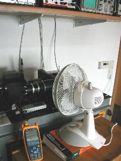
22.02.2006: The required changes in circuit for higher input voltage (equaly 14 LiPo) are done. The layout is being developed. We hope we can make first tests in April. 21.02.2006: The suspected cause for resonances on the test-bench is found! At about 14.000rpm (at the LEHNER-motor), the clutch on the slow turning shaft of the reduction gear disintegrated. The broken parts indicate pre-existing cracks. No other explanation is possible, beacause the clutch normally can transfer (was able to!) about 100Nm according to the data sheet (we worked in the area of only 10Nm...) We ordered a replacement which will arrive later this week. 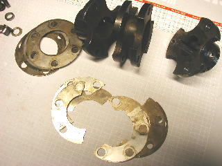
31.01.2006: New motor! New measurements! LEHNER provided us with a LMT3060-8-14 (THANK YOU!). This motor was a challenge at first for our SLS, because even at star connection it has very low inductance (more a short circuit than inductance ;-) ...) but only this way the motor can achieve the desired RPM, which can be seen on the data sheet. First we choose a PWM-frequency of 50kHz, to hold the current ripple as low as possible over the inductance. Sure, this affects the switching losses in a negative way, but helps to optimize the remaining parameters of the current controller. When the optimization was done, we were able to choose PWM-frequencies between 25kHz and 50kHz in ongoing operation(!) without danger to cause controller damage or encounter any problems. The measurement results in the operation point: 9.000rpm/1,5Nm -> P_shaft=1.413W; Uin=35V Iin=44A -> P_in=1.540W; ETA=91%(!) at 35kHz PWM. We congratulate LEHNER for this motor! The motor can (unfortunately) only operate far below its max. RPM (at 35V in star connection ca. 21.000rpm should be possible) - at higher RPM our test-bench mechanics tend to resonate ... The measurement was performed at 43% partial load. The achieved max. power was maintained for several minutes without forced cooling for SLS2000 or motor. The SLS2000 and motor have been in permanent operation for more than a hour (at changing load and RPM). Extrapolated to the max. RPM of the LMT3060-8-14 at 35V and constant torque (means also motor current) we can expect a shaft-power of P_out=3.500W. With the SLS4000 (doubled motor current) that are theoretically 7.000W! Without additional SLS- or motor-cooling this is not recommended for a long period of time ... 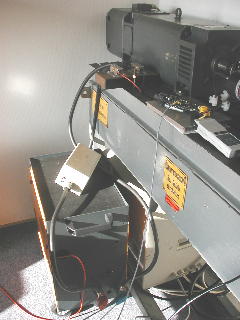
14.01.2006: We finished our new DC-source: Voltage in range of 0..40V and a settable current limit up to 250A will make the work on the test-bench more comfortable! At a output voltage of 40V it should permanently permit up to 150A. we were able to test only up to 70A, because we don't have a adequate load. But this without any problmes for a longer period of time! The undersized connection from power supply to SLS was limiting (from the 40V barely 36V got to the SLS ...). More crossection should help out of this situation. The motor also heats relatively fast (no airflow!), this strongly limits measurements on the test-bench - We must install a motor cooling (e.g. fan) here. We tested a big TORCMAN (TM685-40PRO14-9w) with a small SLS2000 at a PWM-frequency of 35kHz. The SLS2000 consumed about 2500W electrical power and the motor shaft power was measured about 2200W (8.100rpm at 2,6Nm). The system efficiency (SLS2000+motor) was about 88% - and this in partial load!!! Measurement inaccuracy not taken into account, but trustworthy. For the small SLS2000 a good result anyways! ... and the SLS4000 has even more potential! 02.01.2006: A happy new year! The poll started in early december regarding higher input voltage resulted in more work for us ;-) You voted clearly for higher voltage! OK, it did not surprise us. At the appropriate time we will take on this task. But first we need to focus our attention to the SLS market launch for the exhibition in Sinsheim in March! On time before Sinsheim we want to present our sell prices here on our homepage. ... Development 2005 ... (click here...) |