
| SinusLeistungsSteller - RPM-/torque controller |
|
Rotation Speed (RPM)-/Torque Controller: The SinusLeistungsSteller can either control the speed or torque of the motor. The following diagram illustrates this relationship. To the right, the speed is plotted; up the torque. This diagram can be easily transferred from the mechanical to the electrical "mindset", considering first an ideal motor (eta = 1): The rotation speed corresponds with the induced voltage and the torque corresponds with the motor current. Important: this is the current in the motor phases; so it is not equal with battery current, used in the modelbuilder scene! 
The power can be represented in both ways of thinking by hyperbolic curves. All points on a hyperbole represent operating points of equal power. Additionally to this, a characteristic curve for a propeller is plotted (red solid line). For propellers the torque increases by square with the rotation speed - it is therefore a parabolic curve. The red dashed line represents a faster rotating propeller (small diameter or low pitch). This propeller produces the same power, but at higher speed. The torque decreases in inverse proportion to the increase of the rotation speed - compared with the other propeller. 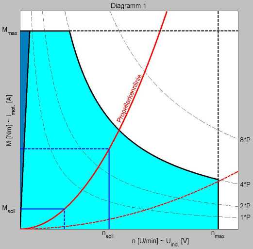
The SLS can be configured to fit a SOA (Safe Operating Area; in the diagram turquoise background), customized to a specific motor: By limiting to n(max) it is prevented, that the motor overspeeds and thereby takes mechanical damage. With M(max), the motor current is limited to a value, which represents the thermal limit of the motor. Theoretically the SLS can even be limited to a maximum power, which is e.g. beneficial with the use of constant speed propellers. The dark triangle on the left within the SOA represents the area, which is not achievable without motor sensors. Maximum torque is only available above a minimum rotation speed, but this not a problem with propellers, since propeller curves do not cross this area. With this, the SOA is defined as the outer frame within a motor can be used. The propeller further limits the operating points of the motor: only the operating points that are actually located on the propeller curve are possible. The speedup (also the speed down) of the motor proceeds along this propeller curve. With the SLS it is possible to specify either the rotation speed n(soll) or the torque M(soll) as a setpoint to be controlled without influence of actual load condition. The other variable follows the propeller curve and adjusts itself accordingly. In practice, the propeller curve changes dynamically with different airspeed of the model! So it is easy to understand that a fast flying model must expend less power to produce a certain rotation speed of the propeller, as for a model, that has to reach the same rotation speed in static thrust. This is shown in the following diagram: 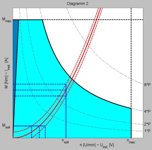
Depending on the application, the user can choose between torque- or RPM-control: For a helicopter drive e.g. it is very desirable to control the rotor at a constant speed - regardless of the pitch position. At a constant rotation speed of the main rotor, reacting torque will not occur. This reacting torque would tend the helicopter to turn around its vertical axis. This would be needed to be balanced manually - with constant speed this is not necessary. In this way the helicopter is more stable in the air and can be controlled easier and more precisely! In a RC car (like our monster truck) however, it is better to control torque. In this case, the stick position of the remote control is considered as the setpoint M(soll). As a result of this, a more natural driving behavior is achieved - with unchanged stick position, the speed adapts on a hill-up/down automatically. Acceleration processes can be controlled more sensitively. ... at this point some details about Control Engineering: In the language of a control engineer, the Field-Oriented Control (FOC) is called as a structure of "speed control loop with nested current control loop". That means that both the current as well as speed have their own control loop (with seperate setpoints and feedback), which are nested. This means further: each loop can be given a seperate setpoint - in other words a desired speed and desired motor current. However, the overall system can control only one of these two set points - depending on which is reached first. Example: If the current setpoint value is reached first, than this current will be controlled or limited, but the desired speed, will not be reached because the setpoint for the motor current (=torque) is given to small to achieve a higher speed. If we increase now the setpoint for the motor current, it is controlled to a higher motor current, which in turn results in a higher speed, if no change of the load situation takes place. With further increase of the motor current, the desired speed is achieved at some point. The system now settles to this target speed. Increase in the motor current beyond this point does not change, neither the actual speed nor the actual current. Changes of target speed will be controlled as long as the actual motor current is within the limits of the motor target current. From this it can be seen that only one of the setpoints takes effect. Only the motor current or the speed is controlled. However, the non active setpoint can be seen as a limit. In the example above, the speed would be limited to the selected target speed, when the motor load decreases! The system would respond with an increase in speed during load reduction, since higher RPM is associated with a higher motor current - and the unchanged first setpoint value of the motor current remains effective. In other words: the system would try to reach the desired motor current by increasing the speed. This could lead to over-speed and to the destruction of the motor (if no speed-limit is set)! So the FOC offers two operating modes: - RPM-control with motor phase-current-limitation - motor phase-current-control with RPM-limitation Since the motors phase-current (electrical view) corresponds directly to the torque (mechanical view) we also distinguish: - RPM-control with torque-limitation - torque-control with RPM-limitation A "switch-over" is possible between those two modes. Even during operation! If both target points are set correctly. A motor overload through to high RPM or motor AC-currents is nearly impossible, if both target values are set inbetween the nominal value of the used motor. RPM is not dependent upon the load situation thanks to the rotation speed control of the FOC. Even during operation, if e.g. in a helicopter model the pitch is increased (for more power) the RPM remains stable. In this case the motor overload (by requesting to much extra power) can not happen, because of the current limitation that works in the background. |